Test technology 4.0
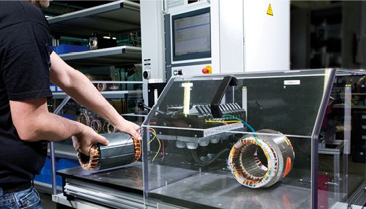
Thanks to the patented SCHLEICH surge voltage test the fully-automatic MTC3-stator testers inspect your windings for possible insulation faults in a fast and reliable way.
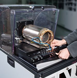
As soon as the test object has been connected, the test starts to run and the connections and test methods are automatically switched -over. The MTC3 evaluates every single test step. At the end of the entire test run it generates a clear and reproducible GO/ NoGO statement.
For measuring, controlling and saving purposes we always insisted on the integration of PCs in our winding testers. By using the proven Microsoft®-technology we are able to offer a clear test result overview to the operator and a variety of input- and configuration possibilities for the installation personnel.
Numerous statistical analyses support your quality assurance. Thanks to the variety of possible reports you can demonstrate your proven quality to your customers.


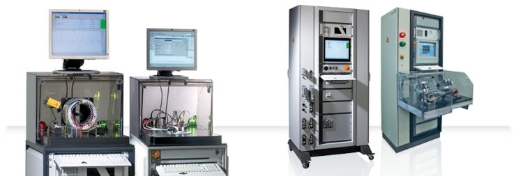
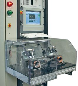
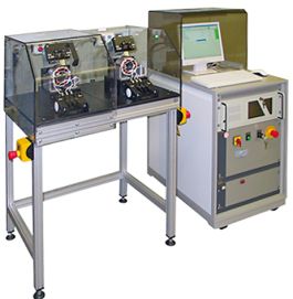
The MTC3 testers are manufactured according to your requirements and requested number of winding connections. For the stator test, we can easily integrate all requested test methods totally according to your requirements. It makes no difference if you require a manual or automatic single-, double- or multi test station, which is delivered either with or without test cover or table. Tests in automated production lines are also possible with our MTC3-testers.
Thanks to the great flexibility of soft-and hardware it´s possible to provide a cost-effective tester which fulfills all your expectations.
Test capabilities
The MTC3 is controlled by the integrated industrial PC. The software allows full-, semi-automatic and manual inspections. In case a fault in the test object is to be determined and located, the tester provides the manual single tests. Thus, the MTC3 offers clearly more, than a standard tester for series production.
1. Fully-automatic test
The test sequence consists of several single test steps. Each test step consists of a test step (e.g. surge voltage) as well as set values and tolerances. After switching-on the tester the single test steps are fully-automatic run one after another and without interruption. At this, each test step is automatically evaluated and the overall result is displayed at the end of the test.
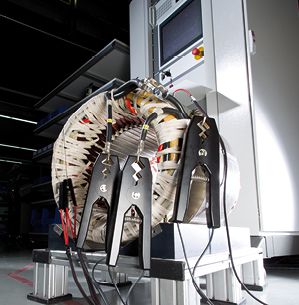
At testers with e.g. 6 winding connections the tester automatically switches between these connections. This is the precondition for the automatic test run.

2. Semi-automatic test
The test sequence consists of several single test steps. Each test step consists of a test step (e.g. surge voltage) as well as set values and tolerances.
After switching- on the tester, the operator selects the test step to be run. He may, for example, contact the lamellas of an armature with test probes and start the test with this test step.
The tester displays the current measured value in large digits in the lower part of the screen. As soon as the operator presses a button, the set values are automatically compared with the measured values and immediately evaluated. Afterwards the operator selects another test step and so on until test results from all test steps are available. The test steps may even be repeatedly tested. It´s also possible too interrupt the test sequence and continue at a later time.
The semi-automatic test is based on a pre-defined test sequence with fixed test steps, set values and tolerances, which, however, may be manually carried out by the operator in any arbitrary order.

3. Manual test
There´s no specified test sequence.
The operator accesses single test methods (e.g. surge voltage- or resistance test...)and switches the test method to any arbitrary connection clamp of the test object.
During the test, the measured values are displayed in large digits. As soon as the test is finished, the measured value is taken-over in a summary of all measured values.
The operator may also run single measurements, as if he had single testers for each test method, and collect the results in a summary. The results may then be saved and printed.
Evaluation of surge voltage
| Tolerance band method |
The surge wave has to be within a programmable tolerance band. |
| Patented Correlation method |
The relation between reference surge wave and currently measured surge wave is automatically determined and the deviation is indicated in %. |
| Error area (EAR) |
The error area between reference surge wave and currently measured surge wave is automatically determined and the deviation is indicated in %.
|
| Difference in area |
The area difference between reference surge wave and currently measured surge wave is automatically determined and the deviation is indicated in %. |
| Attenuation method |
The deviation in the attenuation course between reference surge wave and currently measured surge wave is automatically determined and indicated in %. |
| Frequency method |
The difference in frequency between reference surge wave and currently measured surge wave is automatically determined and indicated in %. |
| Automatic phase comparison |
The tester automatically measures the 3 connection combinations of a DC winding and indicates the 3 surge waves in different colors on the screen. |