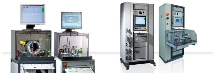
MTC3
Universal winding testers for production — Surge voltage test with 6 KV or 15 KV
Key-Facts
Surge voltage in perfection.
- Inspection of stators, rotors, transformers and chokes
- Shortest rise time 60 ns
- Fully-integrated partial discharge test according to IEC 61934 and DIN EN 60034-18-41
- Resistance measurement in 4-wire technology with temperature compensation
- Insulation resistance test with automatic PI-measurement
- Inductance test | LCR-inductance measuring bridge
- High-voltage test AC according to VDE-standard
- Partial discharge HVAC
- Insulation test DC
- Precise 4-wire resistance test with temperature compensation up to µΩ-range
- Rotary field test with static probe
- Expandable up to 150 connections
- Temperature probe test for 1, 2, 3 … x probes
- Automatic test with subsequent Go/ NoGo - comparison
- Fast & precise measurements with the latest DSP-Technology (Digital Sensor Processor)
- Freely-programmable in- & and outputs
- Integrated high-quality industrial-PC with Windows®7 or Windows®10
- Central database for millions of test squences and results -SQL-server
- Extensive statistical analyses – Trending, Gaussian distribution, FPY…
- Traceability for all test object´s components
- User administration
- Configurable test report printout
- Freely configurable label print for thermal transfer printers
- Several label printers addressable
- Reading of any 1D- and 2D-barcodes
- Remote control: RS232, SPS, Profibus, Profinet, CAN, DeviceNet, Ethernet, EtherCat, USB…
- Full network connectivity
- Data exchange with ERP- and CAQ-systems
- Connection to MES-systems
- Ideal OEM-conditions for easy integration in automatic lines
- Remote maintentance and remote calibration possible
Description
Test technology 4.0
Thanks to the patented SCHLEICH surge voltage test the fully-automatic MTC3-stator testers inspect your windings for possible insulation faults in a fast and reliable way.
As soon as the test object has been connected, the test starts to run and the connections and test methods are automatically switched -over. The MTC3 evaluates every single test step. At the end of the entire test run it generates a clear and reproducible GO/ NoGO statement.
For measuring, controlling and saving purposes we always insisted on the integration of PCs in our winding testers. By using the proven Microsoft®-technology we are able to offer a clear test result overview to the operator and a variety of input- and configuration possibilities for the installation personnel.
Numerous statistical analyses support your quality assurance. Thanks to the variety of possible reports you can demonstrate your proven quality to your customers.


The MTC3 testers are manufactured according to your requirements and requested number of winding connections. For the stator test, we can easily integrate all requested test methods totally according to your requirements. It makes no difference if you require a manual or automatic single-, double- or multi test station, which is delivered either with or without test cover or table. Tests in automated production lines are also possible with our MTC3-testers.
Thanks to the great flexibility of soft-and hardware it´s possible to provide a cost-effective tester which fulfills all your expectations.
Test capabilities
The MTC3 is controlled by the integrated industrial PC. The software allows full-, semi-automatic and manual inspections. In case a fault in the test object is to be determined and located, the tester provides the manual single tests. Thus, the MTC3 offers clearly more, than a standard tester for series production.
1. Fully-automatic test
The test sequence consists of several single test steps. Each test step consists of a test step (e.g. surge voltage) as well as set values and tolerances. After switching-on the tester the single test steps are fully-automatic run one after another and without interruption. At this, each test step is automatically evaluated and the overall result is displayed at the end of the test.
At testers with e.g. 6 winding connections the tester automatically switches between these connections. This is the precondition for the automatic test run.

2. Semi-automatic test
The test sequence consists of several single test steps. Each test step consists of a test step (e.g. surge voltage) as well as set values and tolerances.
After switching- on the tester, the operator selects the test step to be run. He may, for example, contact the lamellas of an armature with test probes and start the test with this test step.
The tester displays the current measured value in large digits in the lower part of the screen. As soon as the operator presses a button, the set values are automatically compared with the measured values and immediately evaluated. Afterwards the operator selects another test step and so on until test results from all test steps are available. The test steps may even be repeatedly tested. It´s also possible too interrupt the test sequence and continue at a later time.
The semi-automatic test is based on a pre-defined test sequence with fixed test steps, set values and tolerances, which, however, may be manually carried out by the operator in any arbitrary order.

3. Manual test
There´s no specified test sequence.
The operator accesses single test methods (e.g. surge voltage- or resistance test...)and switches the test method to any arbitrary connection clamp of the test object.
During the test, the measured values are displayed in large digits. As soon as the test is finished, the measured value is taken-over in a summary of all measured values.
The operator may also run single measurements, as if he had single testers for each test method, and collect the results in a summary. The results may then be saved and printed.
Evaluation of surge voltage
| Tolerance band method | The surge wave has to be within a programmable tolerance band. |
| Patented Correlation method | The relation between reference surge wave and currently measured surge wave is automatically determined and the deviation is indicated in %. |
| Error area (EAR) | The error area between reference surge wave and currently measured surge wave is automatically determined and the deviation is indicated in %. |
| Difference in area | The area difference between reference surge wave and currently measured surge wave is automatically determined and the deviation is indicated in %. |
| Attenuation method | The deviation in the attenuation course between reference surge wave and currently measured surge wave is automatically determined and indicated in %. |
| Frequency method | The difference in frequency between reference surge wave and currently measured surge wave is automatically determined and indicated in %. |
| Automatic phase comparison | The tester automatically measures the 3 connection combinations of a DC winding and indicates the 3 surge waves in different colors on the screen. |
Applications
Pioneer in functionality and measuring accuracy.
MTC3 with dual test cover
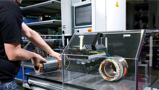
- 4-wire contacting with central handle for opening all clamps at the same time
- VA-plate to contact the stator
MTC3 to inspect larger stators
MTC3 in a production line
- Fully-automatic line
- Fully-automatic contacting
- Communication with PLCs
- Communication with ERP-systems
MTC3 with mounted dual test cover
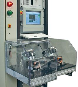
- Dual test station for compressors
- Solid industrial test cover - designed for millions of moves - no plastic construction- solid aluminium frame with longlife-linear guide
Dual test table
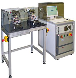
- Dual test cover for compressors
- Solid longlife-industrial test cover- no plastics
Contacting
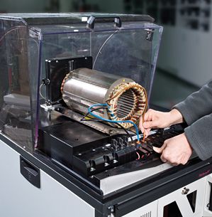
- Integrated 4-wire clamps in the front
- Result light on both sides of the clamps
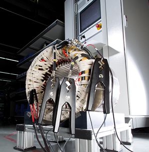
MTC3 use in electric workshop for rail drives

- Inspection of free-standing stators
- If requested, manual inspection with test probes
- 2- hand start
- 4-wire measuring technology
Technology
Benefits at a glance.
Connections
- Standard model: 3 plus laminated core (ground connection)
- Optional: up to 24 connections
- All connections freely programmable via matrix
Measuring technology
- Precise and fast measurements
- TRMS » true R.M.S. measurement
- R.M.S.- and peak value measurement
Autotest
- automatic stator-, and motor inspection
- fully-automatic fault analysis
Surge voltage
- 6 KV or 15 KV
- Automatic and manual surge voltage test
- Automatic evaluation
- 8 different evaluation methods incl. correlation (SCHLEICH-patent)
High-voltage DC
- 6 KV or 15 KV
- Manually adjustable
- Automatic programmable
- Step voltage measurement
Insulation resistance DC
- 6 KV or 15 KV
- According to VDE 0701
- 1 MΩ-100 GΩ
Polarization index
- 6 KV or 15 KV
- PI-measurement
- DAR-measurement
- Automatic measurement
Partial discharge surge - option
- 6 KV or 15 KV
- According to DIN EN 60034-18:2014
- Measurements of
- PDIV - Partial discharge inception voltage
- RPDIV - Repetitive partial discharge inception voltage
- RPDEV - Repetitive partial discharge extinction voltage
- PDEV - Partial discharge extinction voltage
- Measurements via coupler in the test lead- perfect for motors
- Measurements via antenna - perfect for stators
Resistance- Option
- 1 μΩ-100 kΩ
- imbalance inspection
- Precise 4-wire technology
- ambient temperature compensation
- object´s temperature compensation
- temperature sensor test
High-voltage AC - Option
- Up to 6 KV, up to 1 A
Partial discharge HVAC - Option
- Up to 6 KV, up to 1 A
- Measurement between phases (dependent from the test object´s switching mode)
- Measurement between phases and laminated core
Rotary field- Option
- Rotary field test with static test probe
- For 1- and 3-phase-motors
- For pole-changeable motors
- Suitable for segregated windings
Inductance- Option
- Inductance measurements via integrated measuring bridge
- 4-wire technology
Impedance - Option
- Impedance measurement via integrated measuring bridge
- 4-wire technology
Capacity - Option
- Capacity measurement via integrated measuring bridge
- 4-wire technology
PE/ Ground AC - Option
- PE/ Ground resistance, measured with AC
- 10-200 A AC, adjustable, electronically controlled
- Current steps 1 A
- 6, 12, 18, 24 V AC
⇒ More details available under Download.
Accessories


For further information please contact our technical sales also contact us by phone