EncoderAnalyzer
Inspecting and adjusting encoders, resolvers, multiturn encoders and hall elements

Key-Facts
All in One - Encoder analysis.
- Encoder analysis without special knowledge
- Automatic inspection of all encoder signals
- Inspection of all signal pulses per revolution
- Determination of number of pulses per revolution
- Inspection of all 90degree-phase shifts between signals per revolution
- automatic inspection of all signal voltages per revolution
- Sense of rotation and encoder speed
- Angle fault per revolution
- Angle balance of rotary encoders
- EMF-measurement at all three motor phases to adjust resolvers, encoders or hall elements
- Storing the angle offset in the rotary encoder via data interface
- EMF-measurement to determine the ke-value (voltage constant) during run-out and standardization to 1000 rpm
- EMF-symmetry measurements during run-out
- Incremental encoder test with A - /A - B - /B - Z - /Z channels
- Sine- Cosine-rotary encoder test with sin - /sin - cos - /cos - N - /N channels
- Resolver-tests
- Hall element-test, evaluation of the three commutation signals
- Encoder interfaces via SSi, EnDat, Hiperface
- Measuring module with 6 or 12 high-speed-measuring channels
- Integrated adjustable voltage supply for encoders
- Integrated reference signal source for resolvers
- Windows®-Software to evaluate the measuring signals
- Measuring signals displayed similar to an oscilloscope
- SQL-database for encoder types, sorted by manufacturer and type
- Multilingual user interface
Description
The functional principle - genious and simple.
Modern drives are often equipped with rotary encoders. For the operator, a detailed inspection is made difficult due to the large diversity of encoders in the market. This applies in particular for repairers of electric motors but also for analyses in production. An extensive inspection without special measuring technology is not possible.
The EncoderAnalyzer offers valuable services by simplifying the encoder inspection as it supplies the encoder with voltage and measures all signals. Afterwards they are automatically evaluated. The result is indicated either as a clear GO (o.k. ) or a clear NOGO (not o.k.).
The following rotary encoders and sensor systems may be inspected:
- Incremental square wave encoders with A, /A, B, /B, N, /N, U, /U, V, /V, W, /W6-channel EncoderAnalyzer
-
Sine-cosine encoders with sin, /sin, cos, /cos, N, /N
-
Hall elements with A, /A, B, /B, N, /N
-
Hall elements with U, /U, V, /V, W, /W
-
Commutation signals / block commutation
-
Multiturn-absolute encoders with SSi- and Hiperface-interface
-
optional resolvers
-
optional 3-phase motor current measurment during operation
-
optional EMF-voltage measurement up to 700V
-
optional resolver adjustment regarding the moto´s EMF
-
optional programming the rotary encoder´s angle offset
The functional principle.
The EncoderAnalyzer consists of two components: The measuring module and the analysing software, which is to be installed on a PC.
The measuring module provides a connection for the encoders to be inspected. Furthermore, additional components for supplementary measuring functions may be connected to the measuring module.
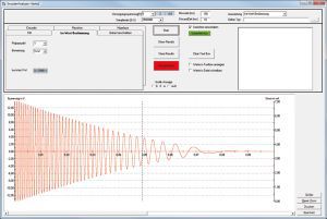
The measuring module performs the tests. For this, it determines millions of measuring values during one revolution and transfers them to a PC. The communication between measuring module and PC is done by a Gigabit-Ethernet connection. By means of the analyzing software the measured results are automatically evaluated. At the end of an inspection the software presents the result on the screen. For a better understanding, errors detected at a broken rotary encoder, are graphically displayed like in an oscilloscope.
The test results are stored in a database. If requested, a detailed test report may be printed.

Connecting the rotary encoder
The rotary encoder to be inspected is connected with the measuring module by a measuring lead. On the measuring module´s front side up to 2 measuring sockets are available for the connection of the measuring leads. verbunden. The number of measuring sockets depends on the ordered options. The EncoderAnalyzer with all 12 measuring channels is equipped with 2 measuring sockets.
A voltage supply of 3...30 V is also integrated in the EncoderAnalyzer. Depending on the encoder, voltage level and maximum permissible power consumption are entered by the operator via software input. During the measurement the EncoderAnalyzer monitors the power consumption. In case the maximum permissible value is exceeded, the voltage supply is automatically switched off.
- Measuring socket MU for
- three high-voltage measuring inputs
- Measuring socket MI for
- three current measuring inputs for current clamps
- Measuring socket MP for
- resolvers
- Measuring socket ME for
- Incremental square-wave encoders
- Sine-cosine encoders
- Hall elements
- Commutation signals/ Block commutation
- Encoder´s voltage supply
- Communication - and programming interface
The analysis software
The fast and intelligent measuring technology and the user-friendly, intuitive analysis software are perfectly matched with each other. Only a few settings and selections are sufficient, to configure the measurement for the encoder to be tested.
The extensive evaluations lead to clear and easy-understandable results. Special or detailed knowhow is not necessary while dealing with the analysis software. The software helps and supports during the connection and evaluation of encoders.
As supplement to the encoder analysis the software also assists during the angle adjustment of rotary encoders. No matter, if the rotary encoder needs to be adjusted by mechanical turning or if only the angle offset needs to be determined, the software graphically supports the operator during the adjustment. Depending on the encoder type and the EncoderAnalyzer´s equipment, the offset angle may also be written in the rotary encoder.
EMF-measurment Resolver signal

Measuring principles for the encoder inspection
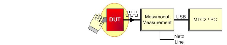
1. Rotary encoder- / Resolver test
The rotary encoder is connected with the measuring module with an appropriate connection lead. Afterwards you manually turn the encoder´s axis. The arising impulses are digitized and evaluated by the measuring module.
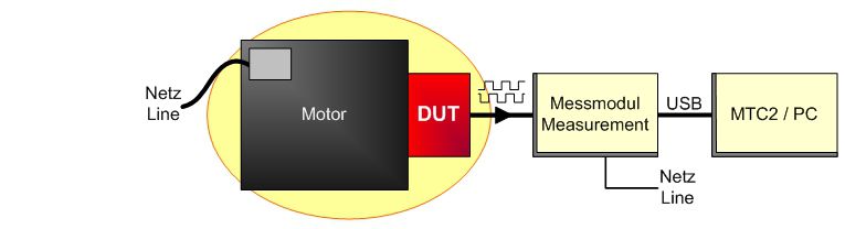
2. Rotary encoder- / Resolver test together with the motor
The rotary encoder mounted on the motor is connected with the measuring module with an appropriate connection lead. Afterwards the motor is directly operated from the mains or via a frequency converter. The arising impulses are digitized and evaluated by the measuring module.
3. Rotary encoder- / Resolver test by means of a test installation
In a special SCHLEICH-test installation the rotary encoder is mechanically coupled with a small drive motor. Via an appropriate connection lead it is connected with the measuring module. For testing purposes the module actuates the drive motor. The arising impulses are digitized and evaluated by the measuring module. Depending on the encoder to be tested the motor´s angle position may also be determined.
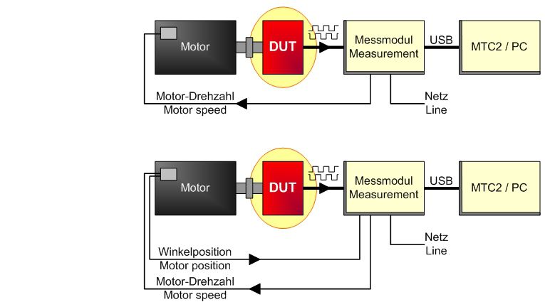
4. Resolver- / Hall element adjustment
For the adjustment the resolver, which is still connected with the motor, is additionally connected with the measuring module via an appropriate connection lead. Furthermore the motor is mechanically coupled by a drive motor. Afterwards the drive motor is directly operated from the mains or, better, by a frequency converter. The arising pulses and the Back-EMF induced in the windings are digitized and evaluated by the measuring module. The measuring module derives the adjustment-information from the measured values which is also indicated on the screen.

Voltage supply for the encoder
For testing purposes, the encoder has to be supplied with DC-voltage which is generated in the measuring module and in the requested voltage level. The supply voltage is shortcircuit proof and the encoder´s power consumption is also inspected. In case the power consumption is too high, the measuring module automatically switches-off the supply voltage due to safety reasons.
Database
The software is equipped with a database with storage capacity for thousands of encoders and resolver.
For the inspection of an encoder, the corresponding data has to be contained in the database. The data consists of relevant information as e.g. the encoder type, the supply voltage level, the pin assignment and so on. Based on this information, the software assists you regarding the suitable connection cable and how to properly connect the encoder.
Furthermore the database contains even more information. Although they are not important for the measurements, they inform about further details of the encoder.
Applications
Encoder inspection in the workshop.
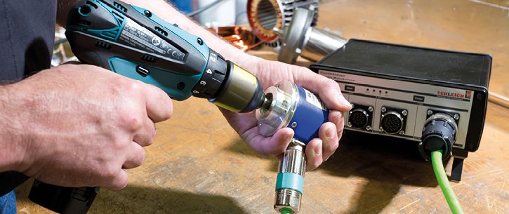
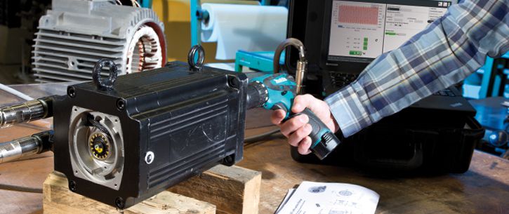
The EncoderAnalyzer is only able to inspect encoders with rotating shaft. For this, the encoder may be directly driven by the motor at which the encoder is installed.
But also in case the encoder is to be inspected separately, it has to be driven by constant speed. For this, as example, a cordless screwdriver can be used.
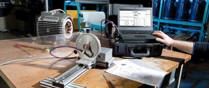
As an alternative, the encoder/ resolver may also be inspected separately on a small test stand. The test stand is equipped with a small motor which drives the encoder with selectable speed. The EncoderAnalyzer collects all signals and determines all parameters. In case target values are entered in the EncoderAnalyzer, an automatic target-actual comparison is done by the software, followed by an evaluation.
Technology
Benefits at a glance.
General information
- Worldwide voltage supply 90–250 V, 47–63 Hz
- Dimensions W 20 x D 20 x H 5 cm
- weight 1 kg
- Operating temperature 10°–50° Celsius
- Storing temperature-20°–60° Celsius
Encoder
- Measuring inputs
- 6 x or optional 12 x analog inputs
- Measuring range 0–30 V
- Measuring signals A - /A - B - /B - Z - /Z
- Measuring signals sin - /sin - cos - /cos - ref - /ref
- Measuring signals K1 - /K1 - K2 - /K2 - K3 - /K3
- 6 x or optional 12 x analog inputs
Resolver
- Excitation output
- 1 x analog output
- Voltage range 0-10 V
- Frequency range1-10 KHz
- 1 x analog output
- Measuring inputs
- 2 x analog inputs
- Measuring range 0–30 V
- Measuring signals sin - /sin - cos - /cos
Single- and Multiturn encoders
- Measuring inputs
- 6 x analog inputs
- Measuring range 0–30 V
- Measuring signals sin - /sin - cos - /cos - ref - /ref
- 6 x analog inputs
- Protocol data interfaces
- Hiperface
- SSi
- EnDat 2.2 - bidirectional
EMF-Measurement
- Measuring inputs
- 3 x analog inputs
- measuring range 0–700 Veff
- internal virtual neutral point
- fuses integrated in the tester
- fuses integrated in the test probes
⇒ More details available under Download.
For further information please contact our technical sales also contact us by phone